- 您现在的位置:买卖IC网 > Sheet目录1214 > EVAL-ADE7754EBZ (Analog Devices Inc)BOARD EVALAUTION FOR ADE7754
�� ��
��
��ADE7754�
�are� particularly� noticeable� at� low� power� factors.� The� ADE7754�
�provides� a� means� of� digitally� calibrating� these� small� phase�
�For� time� sampling� signals,� rms� calculation� involves� squaring� the�
�signal,� taking� the� average,� and� obtaining� the� square� root:�
�∑� f�
�errors.� The� ADE7754� allows� a� small� time� delay� or� time� advance�
�to� be� introduced� into� the� signal� processing� chain� to� compensate�
�for� small� phase� errors.� Because� the� compensation� is� in� time,� this�
�technique� should� be� used� only� for� small� phase� errors� in� the�
�F� rms� =�
�1�
�N�
��
�N�
�i� =� 1�
�2�
�(� i� )�
�(2)�
�V� (� t� )� ×� V� (� t� )� =� V� rms� ?� V� rms� ×� cos(� 2� ω� t� )�
�range� of� 0.1� °� to� 0.5� °� .� Correcting� large� phase� errors� using� a�
�time� shift� technique� can� introduce� significant� phase� errors� at�
�higher� harmonics.�
�The� phase� calibration� registers� (APHCAL,� BPHCAL,� and�
�CPHCAL)� are� twos� complement,� 5-bit� signed� registers� that�
�can� vary� the� time� delay� in� the� voltage� channel� signal� path� from�
�–19.2� μ� s� to� +19.2� μ� s� (CLKIN� =� 10� MHz).� One� LSB� is� equiva-�
�lent� to� 1.2� μ� s.� With� a� line� frequency� of� 50� Hz,� this� gives� a�
�phase� resolution� of� 0.022� °� at� the� fundamental� (i.e.,� 360� °�
�1.2� μ� s� 50� Hz).�
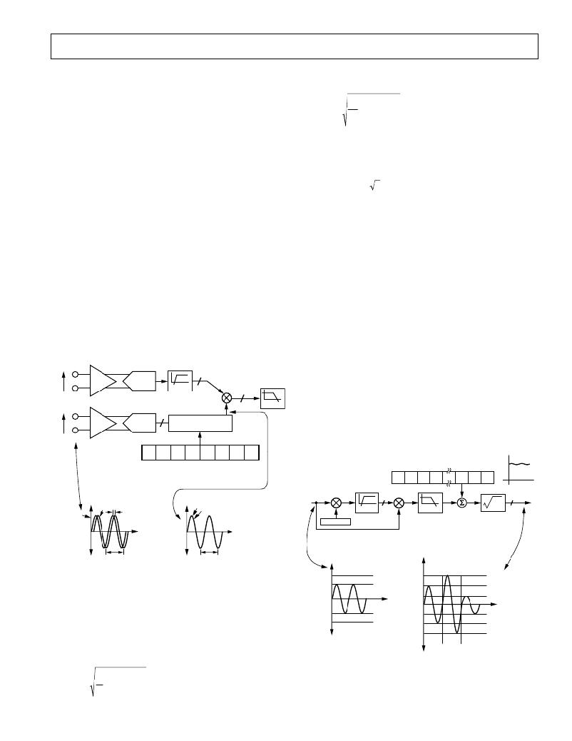
�Figure� 19� illustrates� how� the� phase� compensation� is� used� to�
�remove� a� 0.091� °� phase� lead� in� IA� of� the� current� channel� caused�
�by� an� external� transducer.� In� order� to� cancel� the� lead� (0.091� °� )�
�in� IA� of� the� current� channel,� a� phase� lead� must� also� be� intro-�
�duced� into� VA� of� the� voltage� channel.� The� resolution� of� the�
�phase� adjustment� allows� the� introduction� of� a� phase� lead� of�
�0.086� °� .� The� phase� lead� is� achieved� by� introducing� a� time� advance�
�into� VA.� A� time� advance� of� 4.8� μ� s� is� made� by� writing� –4� (1Ch)�
�to� the� time� delay� block� (APHCAL[4:0]),� thus� reducing� the�
�amount� of� time� delay� by� 4.8� μ� s.� See� the� Calibration� of� a� 3-Phase�
�Meter� Based� on� the� ADE7754� Application� Note� AN-624.�
�The� method� used� to� calculate� the� rms� value� in� the� ADE7754� is�
�to� low-pass� filter� the� square� of� the� input� signal� (LPF3)� and� take�
�the� square� root� of� the� result.�
�With�
�V� (� t� )� =� V� rms� ×� 2� ×� sin(� ω� t� )�
�then�
�2� 2�
�The� rms� calculation� is� simultaneously� processed� on� the� six� analog�
�input� channels.� Each� result� is� available� on� separate� registers.�
�Current� RMS� Calculation�
�Figure� 20� shows� the� detail� of� the� signal� processing� chain� for� the�
�rms� calculation� on� one� of� the� phases� of� the� current� channel.�
�The� current� channel� rms� value� is� processed� from� the� samples�
�used� in� the� current� channel� waveform� sampling� mode.� Note�
�that� the� APGAIN� adjustment� affects� the� result� of� the� rms� calcu-�
�lation.� See� the� Current� RMS� Gain� Adjust� section.� The� current�
�rms� values� are� stored� in� unsigned� 24-bit� registers� (AIRMS,�
�BIRMS,� and� CIRMS).� One� LSB� of� the� current� rms� register� is�
�equivalent� to� 1� LSB� of� a� current� waveform� sample.� The� update�
�I� AP�
�24�
�rate� of� the� current� rms� measurement� is� CLKIN/12.� With� the�
�specified� full-scale� analog� input� signal� of� 0.5� V,� the� ADC� produces�
�IA�
�I� AN�
�PGA1�
�ADC�
�HPF�
�24�
�an� output� code� which� is� approximately� ±� 2,684,354d.� See� the�
�Current� Channel� ADC� section.� The� equivalent� rms� values� of� a�
�VA�
�V� AP�
�PGA2�
�ADC�
�1�
�0.69� AT� 50Hz,� 0.022�
�0.83� AT� 60Hz,� 0.024�
�LPF2�
�full-scale� ac� signal� is� 1,898,124d.� With� offset� calibration,� the�
�current� rms� measurement� provided� in� the� ADE7754� is� accurate�
�within� ±� 2%� for� signal� input� between� full� scale� and� full� scale/100.�
�V� N�
�7�
�0�
�I� rms� (t)�
�0�
�0�
�0�
�1�
�1�
�1�
�0�
�0�
�–100%� to� +100%� FS�
�APHCAL[4:0]�
�IRMSOS[11:0]�
�1CF68Ch�
�–19.2� s� TO� +19.2� s�
�SGN� 2� 11�
�2� 10�
�2� 9�
�2� 2�
�2� 1�
�2� 0�
�00h�
�+�
�24�
�24� IRMS�
�V2�
�V1�
�0.1�
�VA�
�IA�
�VA� DELAYED� BY� 4.8� s�
�(–0.0868� AT� 50Hz)� 1CH�
�IA�
�AAPGAIN�
�HPF�
�LPF3�
�CURRENT�
�SIGNAL� –� i(t)�
�CURRENT�
�CHANNEL� (rms)�
�50Hz�
�50Hz�
�FS�
�Figure� 19.� Phase� Calibration�
�400000h�
�2378EDh�
�+� 122.5%� FS�
�28F5C2h�
�+� FS�
�1CF68Ch�
�+� 100%� FS�
�ROOT� MEAN� SQUARE� MEASUREMENT�
�Root� Mean� Square� (rms)� is� a� fundamental� measurement� of� the�
�00000h�
�147AE0h�
�0000h�
�+� 70.7%� FS�
�AAPGAIN[11:0]�
�magnitude� of� an� ac� signal.� Its� definition� can� be� practical� or�
�D70A3Eh�
�–� FS�
�EB852Fh�
�–� 70.7%� FS�
�mathematical.� Defined� practically,� the� rms� value� assigned� to� an�
�ac� signal� is� the� amount� of� dc� required� to� produce� an� equivalent�
�amount� of� heat� in� the� same� load.� Mathematically� the� rms� value�
�C00000h�
�ADC� OUTPUT�
�WORD� RANGE�
�E30974h�
�DC8713h�
�000h�
�7FFh�
�800h�
�–� 100%� FS�
�–� 122.5%� FS�
�of� a� continuous� signal� f(t)� is� defined� as�
�Figure� 20.� Current� RMS� Signal� Processing�
�F� rms� =�
�1�
�T�
�T�
�×� ∫� f� 2� (� t� )� dt�
�0�
�(1)�
�Note� that� a� crosstalk� between� phases� can� appear� in� the� ADE7754�
�current� rms� measurements.� This� crosstalk� follows� a� specific�
�REV.� 0�
�–15� –�
�发布紧急采购,3分钟左右您将得到回复。
相关PDF资料
EVAL-ADE7755ZEB
BOARD EVALUATION FOR AD7755
EVAL-ADE7758ZEB
BOARD EVAL FOR AD7758
EVAL-ADE7759EBZ
BOARD EVALUATION FOR ADE7759
EVAL-ADE7762EBZ
BOARD EVALUATION FOR ADE7762
EVAL-ADE7763ZEB
BOARD EVALUATION FOR ADE7763
EVAL-ADE7816EBZ
BOARD EVALUATION FOR ADE7816
EVAL-ADE7878EBZ
BOARD EVAL FOR ADE7878
EVAL-ADE7880EBZ
BOARD EVAL FOR ADE7880
相关代理商/技术参数
EVAL-ADE7755EB
制造商:Analog Devices 功能描述:EVAL BOARD ENERGY METERINGW/PULSE OUTPUT - Bulk
EVAL-ADE7755EBZ
制造商:AD 制造商全称:Analog Devices 功能描述:Energy Metering IC with Pulse Output
EVAL-ADE7755EBZ1
制造商:AD 制造商全称:Analog Devices 功能描述:Energy Metering IC with Pulse Output
EVAL-ADE7755ZEB
功能描述:BOARD EVALUATION FOR AD7755 RoHS:是 类别:编程器,开发系统 >> 评估演示板和套件 系列:- 标准包装:1 系列:- 主要目的:电信,线路接口单元(LIU) 嵌入式:- 已用 IC / 零件:IDT82V2081 主要属性:T1/J1/E1 LIU 次要属性:- 已供物品:板,电源,线缆,CD 其它名称:82EBV2081
EVAL-ADE7756EB
制造商:Analog Devices 功能描述:EVAL BD DOCUMENTATION ADE7756 ENERGY METERING IC - Bulk 制造商:Rochester Electronics LLC 功能描述:
EVAL-ADE7757AEBZ
制造商:Analog Devices 功能描述:EVALUATION BOARDS - Bulk
EVAL-ADE7757EB
制造商:Analog Devices 功能描述:EVAL BOARD ENERGY METERINGW/PULSE OUTPUT - Bulk
EVAL-ADE7758ZEB
功能描述:BOARD EVAL FOR AD7758 RoHS:是 类别:编程器,开发系统 >> 评估演示板和套件 系列:* 标准包装:1 系列:PSoC® 主要目的:电源管理,热管理 嵌入式:- 已用 IC / 零件:- 主要属性:- 次要属性:- 已供物品:板,CD,电源